Abstract
An approach is presented for performing site-specific assessment of the impact of construction vibrations on vibration-sensitive facilities. This requires expansion of existing methodologies such that frequency content is included. A case study is included.
Introduction
Many processes involved in advanced technology applications are highly sensitive to vibrations. Among these processes are precision metrology, high-energy physics, long-beam-path laser applications, biotechnology research, and the R&D and production of semiconductors. As areas such as university research campuses, Silicon Valley in the USA, and the Science Parks in Asia become more heavily developed, construction near existing vibration-sensitive facilities becomes unavoidable. This is particularly true as campus-oriented organizations need to add facilities to existing campuses.
Construction activities generate ground vibrations. There is a significant body of literature regarding construction vibrations and their prediction, but virtually none of this lends itself particularly well to the types of assessment appropriate when vibration-sensitive facilities are involved.
This study reviews and compares several forms of vibration limits applicable to construction vibrations and presents the results of a controlled evaluation of construction-related vibrations at a representative site. It includes a methodology for calculating the propagation of spectral data, and methods for determining the site-specific data required for those calculations. To facilitate comparisons with traditional civil engineering methods, it also includes a brief review of that body of literature, as well as an introduction to the forms of data representation prevalent in the analysis of vibration-sensitive facilities.
Ground Vibrations and Their Propagation
Vibrations propagate from a piece of construction equipment through the ground to a distant vibration-sensitive receiver predominantly by means of Rayleigh (surface) waves and secondarily by body (shear and compressional) waves. The amplitude of these waves diminishes with distance from the source. This attenuation is due to two factors: expansion of the wave front (geometrical attenuation) and dissipation of energy within the soil itself (material damping). The rate of geometrical attenuation depends upon the type of wave and the shape of the associated wave front. Material damping is generally thought to be attributable to energy loss due to hysteresis, perhaps caused by internal sliding of soil particles. In addition to other factors (see below), the amount of material damping that occurs is a function of the vibration amplitude; this discussion will be limited to what are generally considered low-amplitude cases.
Material damping in soil is a function of many parameters, including soil type, moisture content and temperature. Clays tend to exhibit higher damping than sandy soils (Wiss, 1967). Wet sand attenuates less than dry sand because the pore water between sand particles carries a significant portion of compressional energy and thus does not subject compressional waves to as much attenuation by friction damping. Propagation of Rayleigh waves is insensitive to the presence or absence of water (Richart, et al.). Frozen soil attenuates less than thawed soil (Barkan).
The general equation modeling propagation of ground vibration from point “a” (a location at distance ra from the source) to point “b” (a location at distance rb from the source) may be stated in the form of Equation (1),

(1)
where γ is a coefficient dependent upon the type of propagation mechanism and α is a material damping coefficient. The propagation equation may be applied to either time-domain or frequency-domain calculations, but care must be exercised that the coefficients are selected properly.
Theoretical radiation models based upon half-space formulation have been used to determine γ corresponding to various propagation models in idealized cases. This form of attenuation can also be expressed in terms of decibels per doubling of distance. Several commonly accepted values of γ are shown in Table 1 for a number of types of sources and waves.
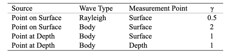
Most construction settings involve surface (or near-surface) sources and receivers, and Rayleigh wave propagation is the most common. Even when the actual vibration source is below the surface—as with pile driving—Rayleigh waves are formed within a few meters of the point on the surface directly above the source, and the propagation can be modeled in terms of Rayleigh waves (Dowding).
There are two principal forms in which investigators have fit Equation (1) to observed data. One approach is to neglect damping attenuation and fit geometric attenuation curves to field data. The other approach assumes Rayleigh wave propagation and fits material damping curves to measured data.
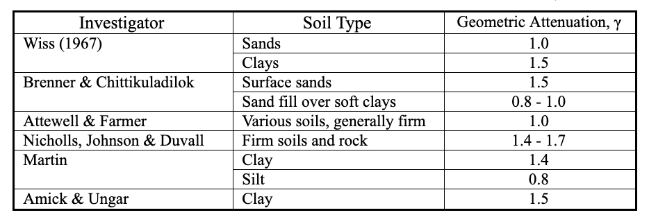
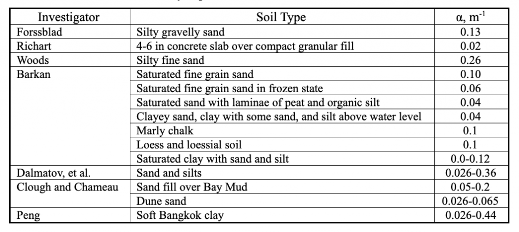
In the first approach, one sets α = 0 and assumes that attenuation follows a straight line on a log-log plot of velocity amplitude as a function of distance. In this case, γ is the slope of that line. Investigators have found values of γ between 0.8 and 1.7. Table 2 summarizes some of the published values of γ. Using the other approach, one sets γ = 0.5 and selects a value of α based upon soil type. Table 3 summarizes some of the published values of α, which range from 0.039 to 0.44 m-1. Using this approach in the traditional manner involves an assumption that the rate of attenuation with distance is independent of frequency.
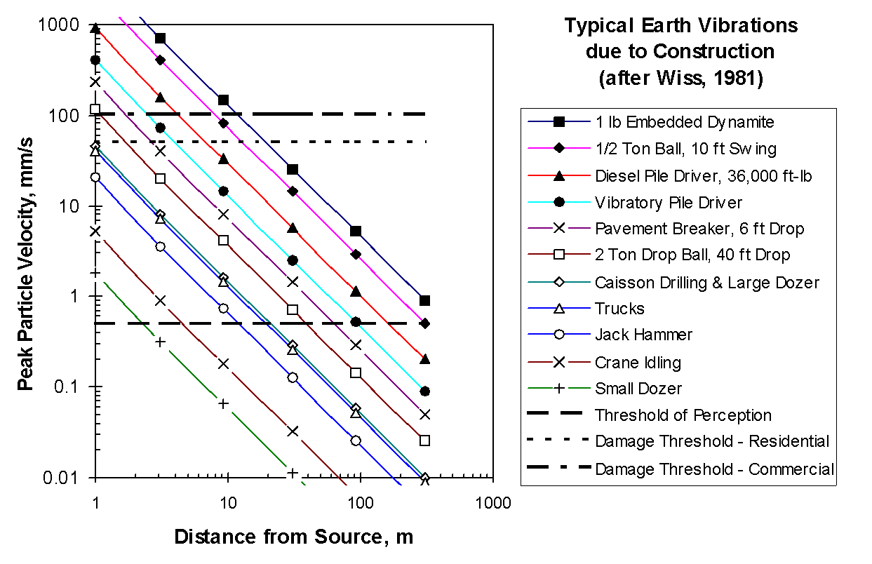
The most common generic model of construction vibrations as a function of distance was developed by Wiss (1981), as shown in Figure 1.
The family of curves presented by Wiss—and other similar constructs based upon the metric of peak particle velocity[1]—provide a convenient means of assessing vibration impact on structures and people, but does not have enough detail to be particularly useful for impact assessment for vibration-sensitive facilities. There is a significant body of knowledge which relates human response and building damage to the peak velocity amplitude measured in the time domain. However, most assessment of the impact of vibrations on advanced-technology facilities is based upon measurement and analysis in the frequency domain, using spectra, as discussed in the following section.
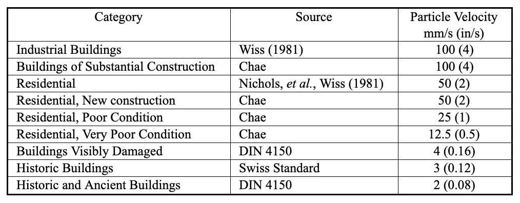
Vibration Criteria for Conventional Buildings
Commonly used criteria for vibration-induced building damage are summarized in Table 4. They are generally assumed to be in terms of peak particle velocity. The DIN 4150 criteria are quite conservative compared to those from other sources with respect to buildings in good condition but are often cited with respect to ancient and historic structures.
Vibration Criteria for Vibration-Sensitive Facilities
Discussion of vibrations can be addressed in three parts: (1) the analytical domain to be used for data representation (time domain vs. frequency domain); (2) the metric to be used (displacement vs. velocity vs. acceleration); and (3) the statistical form, generally a choice between instantaneous amplitude or some sort of averaged amplitude. Construction-related vibrations are almost always discussed in terms of velocity amplitude, as are vibrations being assessed for most vibration-sensitive facilities. However, it is here that the convenient similarities end.
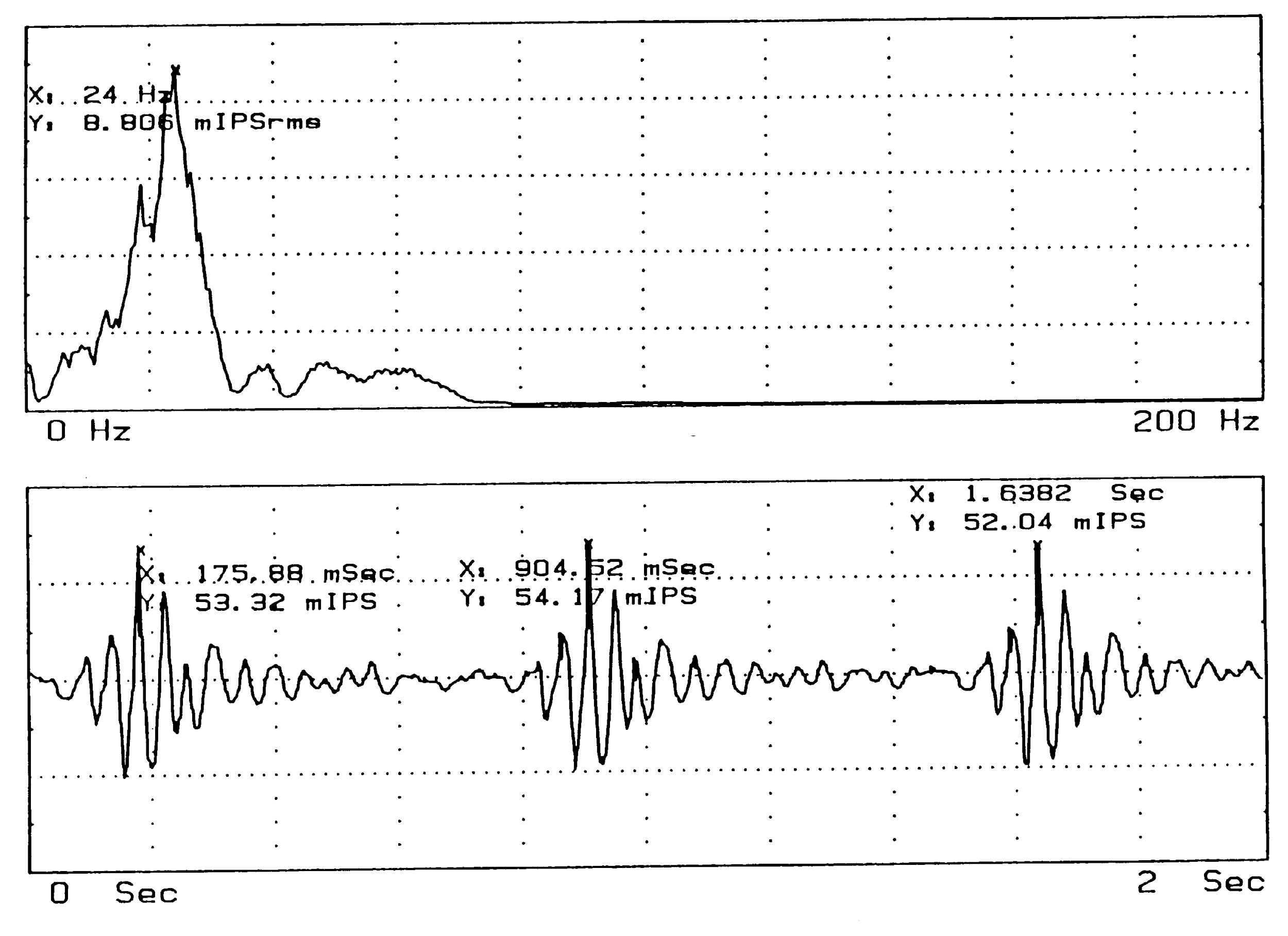
Time-domain data represent vibrations using a “time history,” in which the instantaneous amplitude varies with time. Frequency-domain representation makes use of “spectra” to show the frequency content of a sampled portion of the vibration signal; instantaneous amplitude has no meaning. Figure 2 shows a time history plot and the corresponding spectrum, for vibrations due to pile driving. On a velocity time history plot the instantaneous maximum can be defined over the sample period. On a frequency spectrum, the maximum amplitude can be defined over the frequency range being sampled. In a sense, an amplitude in a spectrum corresponds to the average energy contained in a sinusoid of the given frequency and sample duration. In addition, spectra have associated with them some form of bandwidth, or range of frequencies associated with a point on a spectrum.
It is common practice to characterize vibration-sensitive facilities in terms of generic vibration criteria, developed by Ungar and Gordon (1985) and used extensively. The bandwidth associated with these criteria is the one-third octave band, for which the bandwidth is 23 percent of the center frequency of each band. The one-third-octave band rms velocity criteria are defined in Table 5, after a publication of the Institute of Environmental Sciences and a paper by Gordon.
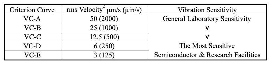
Table 5. Generic vibration criteria for vibration-sensitive facilities.
The frequency content—or spectrum shape—of construction vibrations varies from one type of equipment to another and from one site to another. Construction equipment generates several different categories of vibration waveforms, to which sites may respond in ways determined by the local soil properties. The categories of vibration include:
- Continuous random vibration: Vibrations may cover a wide frequency range. Most excavation and static compaction equipment fall into this category. Tracked vehicles are predominantly of this type but may also exhibit characteristics of high-rate repeated impact due to the tracks hitting the ground.
- Random vibration due to single impact or low-rate repeated impact: This type of vibration results from the soil “ringing” due to sudden dynamic loading. It may include pile driving, blasting, the use of a drop ball, and a “pogo-stick” type of compactor.
- High-rate repeated impact: This is typified by the jackhammer, which generates vibrations at the frequency of impact (such as 19 Hz) and integer multiples of that rate (such as 38 Hz, 57 Hz, etc.)
- Single-frequency continuous vibration: The predominant sources of this type of vibration are vibratory pile driving, pile extraction, and vibratory compaction. They are similar to sinusoidal vibration.
Barkan and Dowding observe that a soil’s material damping provides a specific amount of attenuation per wavelength. This is consistent with observations for many propagation media, but it is not consistent with the use of the coefficient α. Amick has proposed a frequency-dependent soil propagation model—and corresponding field measurement procedures—based upon Equation (1).
Using Amick’s approach, the material attenuation factor α can be defined as a function of frequency in terms of the damping loss factor η, as in Equation (2), where c is the soil wave velocity.

(2)
For a particular soil deposit, both η and c can generally be assumed to represent constant soil properties. Therefore, a quantity made up of the ratio of the two, , can also be considered a constant property of that soil. It can be measured without also having to determine η and c. Thus, a new relationship can be used to define α using Equation (3).

(3)
Equation (1) can be re-written in the new form of Equation (4).

(4)
This is consistent with the approach suggested by Woods and Jedele—who propose a classification of earth materials by attenuation coefficient. Dowding summarizes this in terms of ranges of α at 5 Hz and 50 Hz.
A semiconductor manufacturer planned construction of a new production facility as an expansion of an existing facility, and for production reasons wanted the new facility as close as practical to the existing one. The existing facility was one of its most critical and was in 24-hr production. Construction could not be scheduled around production breaks, but construction activities could not be allowed to degrade quality of the product. A one-day experiment was carried out in which examples of construction equipment being considered for the project were operated on the far side of the parcel of land, with enough buffer to avoid disruption of production. Source spectra and propagation properties unique to this particular site were obtained and used to calculate required setback distances for each piece of construction equipment.
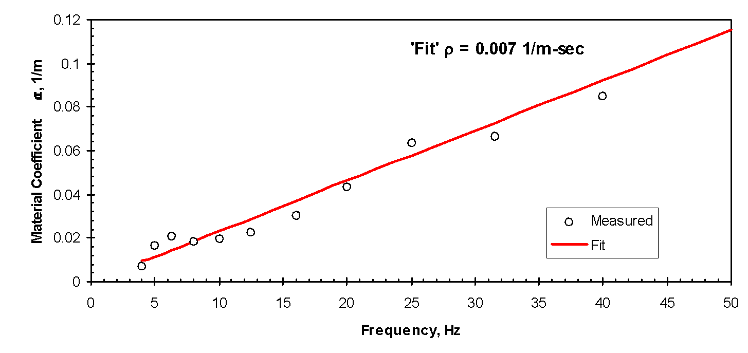
Figure 3 shows values of α that were measured at that site at discrete frequencies between 4 and 40 Hz. The solid line represents the fit of Equation (3) to the data, for which ρ is 0.007 (m-sec)-1.
As discussed earlier, the spectrum shape and predominant frequency can vary significantly from one type of equipment to another. Thus, if attenuation with distance is frequency-dependent, then not all equipment will produce vibrations that attenuate in the same manner. When a study of this sort is carried out, one must evaluate a variety of the equipment that might be used. Some of the equipment examined in this study includes:
- Light excavation equipment
- Heavy excavation equipment, such as scrapers, graders and soil grinders
- Hauling equipment, such as track loaders and dump trucks
- Compacting equipment, including sheepsfoot compactors as well as static and vibratory smooth-drum rollers
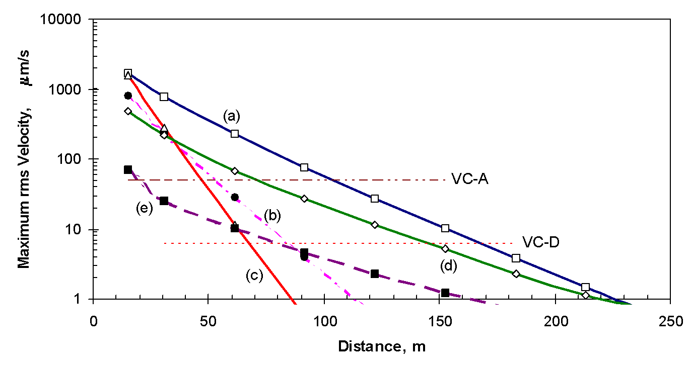
Vibrations were measured at a distance of 15 m (50 ft). Equation (4) and the best-fit relationship for α (shown in Figure 3) were used to predict the vibrations at representative distances from the equipment. Figure 4 shows the manner in which the maximum spectral amplitude decreases with distance for some of the equipment studied. In the case of single-frequency sources (the vibratory compactors) the curve represents the decay with distance of the component at that frequency. In the case of random vibrations such as excavation equipment (which appear as a broad “hump” on the spectrum) the curve represents the maximum spectral amplitude, which tends to shift to progressively lower frequencies as the higher frequencies are attenuated. Table 6 summarizes the setback distances required for the vibrations to be less than VC-A and VC-D.
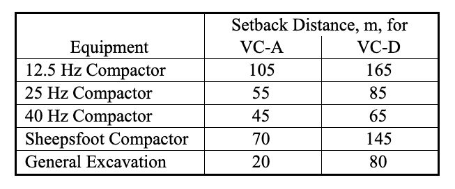
The three vibratory compactors produced nearly the same vibration amplitudes at 15 m. However, the attenuation with distance was dramatically different because of the frequency-dependence of the soil’s damping. The minimum buffer distance for the 12.5 Hz compactor was 2.5 times that for the 40 Hz compactor.
Conclusions
Many processes involved in advanced technology applications are highly sensitive to vibrations, and thus are subject to impact from nearby construction. As areas such as Silicon Valley become more heavily developed, construction near existing vibration-sensitive facilities becomes unavoidable. This is particularly true as campus-oriented organizations need to add facilities to existing campuses. The existing body of literature regarding construction vibrations and their prediction does not lend itself particularly well to the types of assessment appropriate when vibration-sensitive facilities are involved.
Several forms of vibration limits applicable to construction vibrations have been presented, together with the results of a controlled evaluation of construction-related vibrations at a representative site. A methodology was given for calculating the site-specific propagation of spectral data.
The reader is cautioned that the measurement results presented herein are applicable only to the site at which those measurements were made. The methodologies can be used at any site, but the propagation characteristics and vibration performance of specific equipment should be evaluated on a site-by-site basis.
References
Amick, H., “A Frequency-Dependent Soil Propagation Model,” presented at the Conference on Optomechanical Engineering and Vibration Control, Denver, SPIE Proc. Vol. 3786, July 1999.
Amick, H., and Ungar, E. E., “Evaluation of Ground and Structural Vibrations from Pile Driving,” BBN Report No. 6427, January 1987.
Attewell, P. B., and Farmer, I. W., “Attenuation of Ground Vibrations from Pile Driving,” Ground Engineering, v. 3, no. 7, July 1973, pp. 26-29.
Barkan, D. D., Dynamics of Bases and Foundations, translated from the Russian by L. Drashevska, edited by G. P. Tschebotarioff, McGraw-Hill, 1962.
Brenner, R. P., and Chittikuladilok, B., “Vibrations from Pile Driving in the Bangkok Area,” Geotechnical Engineering, v. 5, pp. 167-197, 1975.
Chae, Y. S., “Design of Excavation Blasts to Prevent Damage,” Civil Engineering, ASCE, Vol. 48, No. 4, Apr. 1978, pp. 77-79.
Clough, G. W., and Chameau, J. L., “Measured Effects of Vibratory Sheet Pile Driving,” Journal of Geotechnical Engineering Division, ASCE, v. 106, no. GT10, pp. 1081-1099, 1980.
Dalmatov, B. I., Ershov, V. A. and Kovalevsky, E. D., “Some Cases of Foundation Settlement in Driving Sheeting and Piles,” Proceedings International Symposium on Wave Properties of Earth Materials, pp. 607-613, 1968.
Dowding, Charles H., Construction Vibrations, Prentice-Hall, 1996.
Forssblad, L., “Investigations of Soil Compaction by Vibration,” Royal Swedish Academy of Engineering Sciences, Civil Engineering Sciences, Civil Engineering and Building Construction Series, no. 34, 1965.
German Standards Organization, Vibrations in Building Construction, DIN 4150, 1970.
Institute of Environmental Sciences, “Considerations in Clean Room Design,” IES-RP-CC012.1 (1993)
Gordon, C. G., “Generic criteria for vibration-sensitive equipment,” Proceedings of SPIE Conference on Vibration Control and Metrology, pp. 71-85, San Jose, CA (November 1991).
Martin, D. J., “Ground Vibrations from Impact Pile Driving During Road Construction,” TRRL Supplementary Report 554, Transport and Road Research Laboratory, 1980.
Nichols, H. R., Johnson, C. F., and Duvall, W. I., “Blasting Effects and their Effects on Structures,” Bureau of Mines Bulletin 656, 1971.
Peng, S. M., “Propagation and Screening of Rayleigh Waves in Clay,” Master’s Engineering Thesis no. 386, Asian Institute of Technology, Bangkok, 1972.
Richart, F. E., “Foundation Vibrations,” ASCE Transactions, v. 127, part I, pp. 863-898, 1962.
Richart, F. E., Hall, J. R., and Woods, R. D., Vibration of Soil and Foundations, Prentice-Hall, Englewood Cliffs, NJ, 1969.
Swiss Association of Standardization, “Effects of Vibration on Construction,” Seefeldstrasse9, CH 8008, Zurich, Switzerland.
Ungar, E. E., and Gordon, C. G., “Cost-Effective Design of Practically Vibration-Free High-Technology Facilities,” Proceedings of Symposium sponsored by Environmental Engineering Division of American Society of Civil Engineers, pp. 121-130 (May 1985).
Wiss, J. F., “Damage Effects of Pile Driving Vibration,” Highway Research Board Record 155, 1967, pp. 14-20.
Wiss, J. F., “Construction Vibrations: State of the Art,” Journal of the Geotechnical Division, ASCE, v. 107, no. GT2, Proc. Paper. 16030, Feb. 1981, pp. 167-181.
Woods, R. D., “Screening of Elastic Waves by Trenches,” Journal of Soil Mechanics Division, ASCE, v. 94, no. SM4, pp. 951-979, 1967.
Woods, R. S., and Jedele, L. P., “Energy-Attenuation Relationships from Construction Vibrations,” in Vibration Problems in Geotechnical Engineering (G. Gazetas and E. T. Selig, Eds.), Special Technical Publication, ASCE, New York, pp. 187-202.
Footnotes
-
Peak particle velocity is the maximum 0-peak amplitude in the time domain. Generally, but not always, this refers to the vector sum of the three directional components. ↑
-
As measured in one-third octave bands of frequency over the range 1 to 100 Hz. The criteria are
sometimes relaxed at frequencies below 8 Hz. ↑
H. Amick and M. Gendreau, “Construction Vibrations and Their Impact on Vibration-Sensitive Facilities,” Proceedings of the Sixth Construction Congress, American Society of Civil Engineers (ASCE), Orlando FL, USA, (February 2000), pp. 758-767